Remember children’s fun? Place the mop in the palm of your hand and keep it upright for as long as possible? In control theory, it is known as an inverse pendulum. There is a stick with a weight at the end and a trolley that is supposed to hold this pendulum in an upright position.
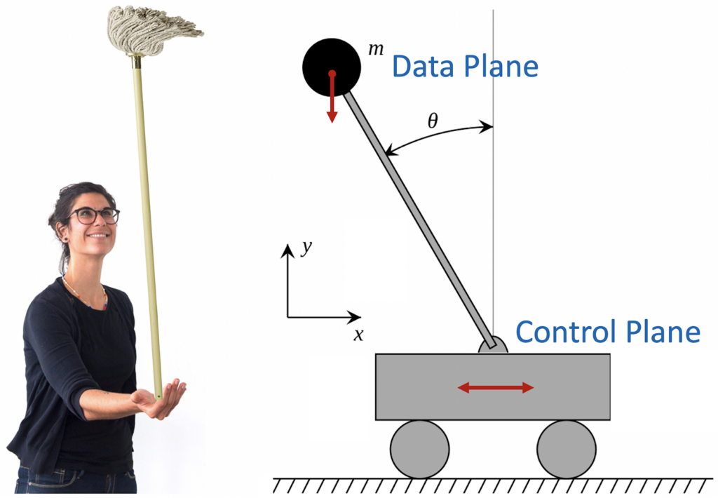
This is a great analogy for modern cloud services. The loaded stick is the Data Plane of the service. Cart – Control Plane. The main task of the Control Plane is to ensure the stable operation of the Data Plane. That is, you need to balance so that the Data Plane is always in a vertical, efficient state. This is not easy – any delays or glitches in the Control Plane will inevitably cause the Data Plane to crash.
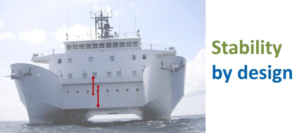
It is easy to make an unstable system, often it turns out somehow. But the consequences can be disastrous. For example, Stockholm has a wonderful museum of the royal ship Vasa. The construction was supervised by the king himself, but despite this, the ship was designed extremely stupidly. It was too narrow and had a very high center of gravity, which led to its instability. After leaving the harbor, due to the wind, the ship gave such a strong heel that it sank within two kilometers.

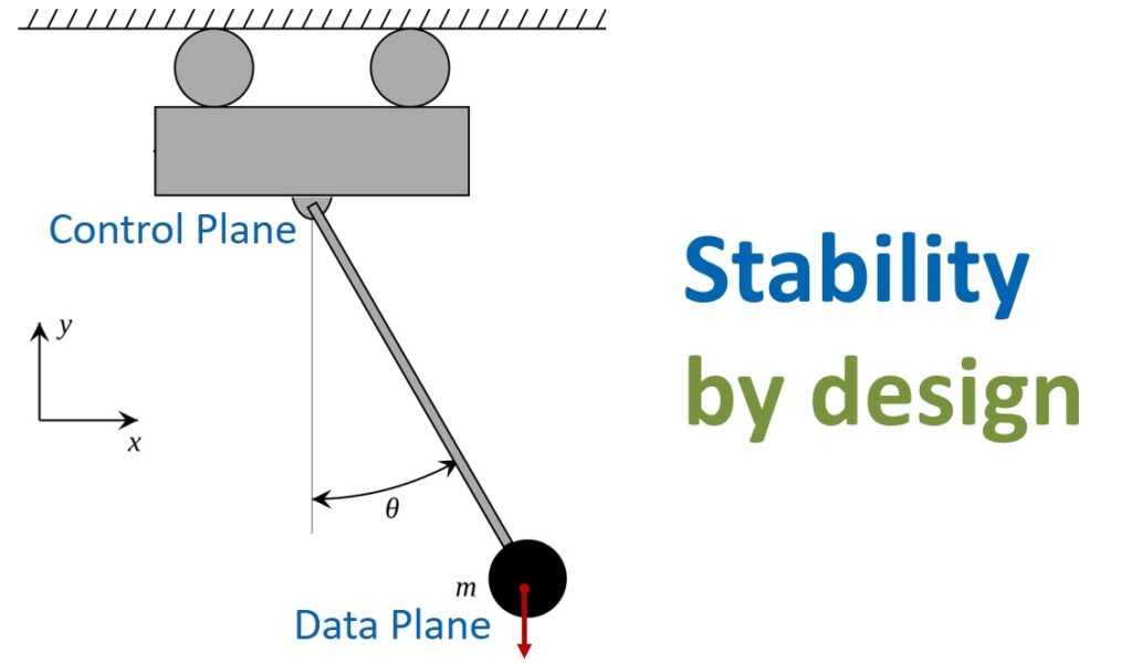
Of course, we don’t want AWS services to be that way. Initially, the architecture needs to be built with stability in which any problems with the Control Plane will not seriously affect the performance of the Data Plane. Continuing the maritime analogy, we can say that services should be like catamarans – non-reversible and unsinkable.
Too big to fail
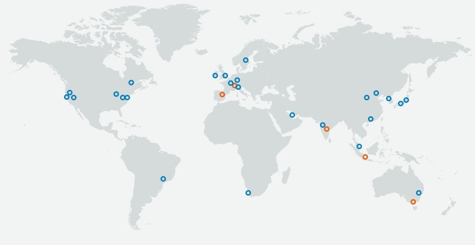
The AWS Cloud currently provides resources in 25 geographic regions. Each region has several Availability Zones (AZ) – these are groups of data centers within a region. In the largest AWS regions, the number of data centers in one AZ reaches eight.
Despite its enormous size, the infrastructure is very reliable. But even in her, sometimes troubles happen. In 2011, 13% of Elastic Block Store (EBS) volumes suddenly became unavailable in the Northern Virginia region. And that’s quite a lot.
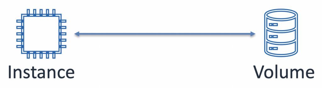
Let’s see what the problem was. EBS is a basic block storage service. For users, this is nothing more than a set of disks that can be connected to virtual machines (Elastic Compute Cloud or EC2).
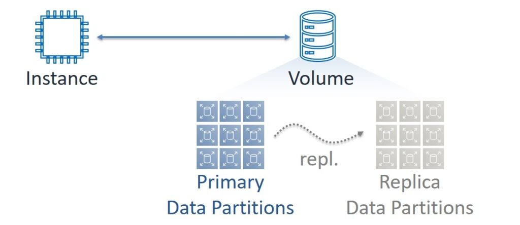
But EBS is built as a distributed and very complex system. If we look behind the first level of difficulty, we will see that each volume consists of many Partitions. They, in turn, have two copies of the data – Primary and Replica. Data writing is always performed in synchronous mode on both copies and reading – only with Primary. In the session on Highload ++, we use the terms Master and Slave, but now the progressive IT community is rejecting them. In order to avoid questions, we will also discard them.
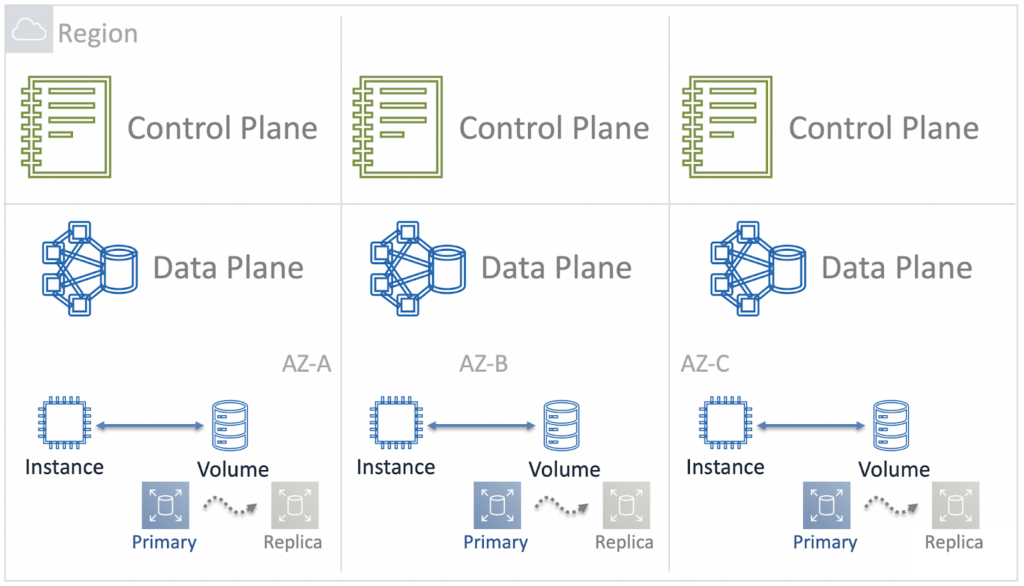
However, both virtual machines and EBS volumes always run in specific Availability Zones. We can say that the Data Plane of EC2 and EBS services is zonal – each AZ has its own independent set of components for transmitting and processing data.
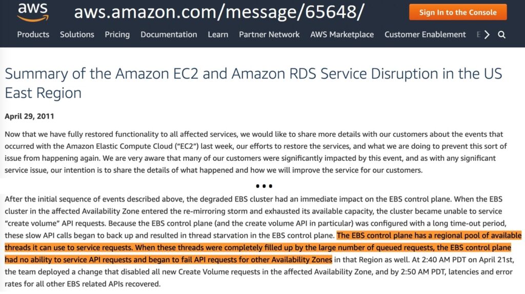
But the Control Plane of the EBS service at the time of the incident in 2011 was regional – and its components were distributed across all Availability Zones in the Region. It was this architectural feature that turned out to be a thin spot when, due to human error, a network failure occurred in one of the Availability Zones.
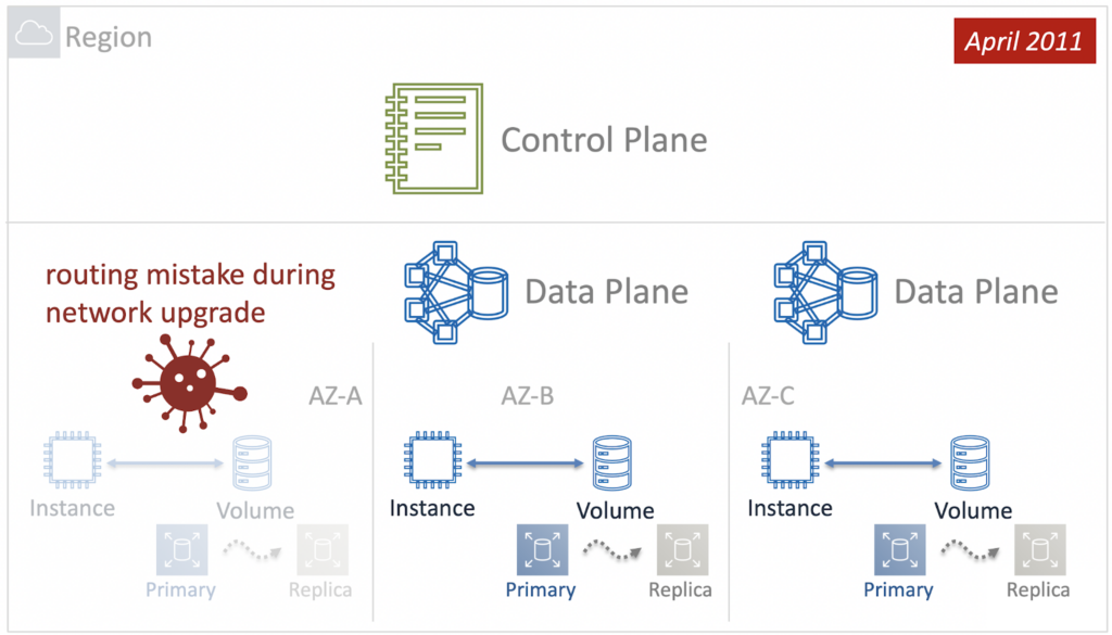
In response to the failure, Control Plane tried to restore the EBS to work and bring back the Primary-Replica pairs. However, the problem was at the network level and the attempt was unsuccessful. In addition, due to the huge amount of volumes that needed to be restored, Control Plane depleted all its resources, and since it was regional, it was unable to process requests from other AZs. And the problem cascaded down to other Availability Zones.
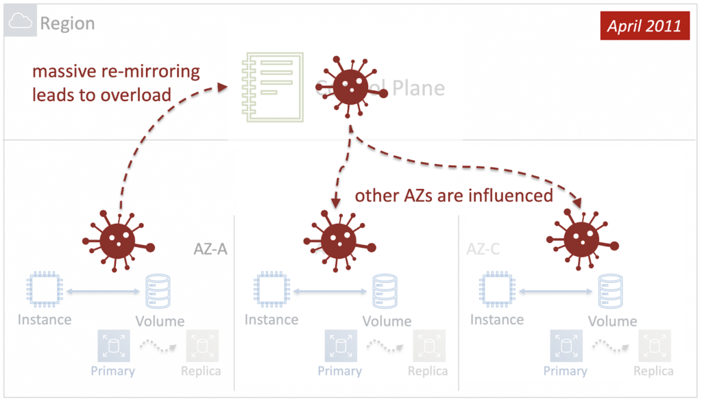
Thus, troubles in one Availability Zone led to a catastrophe at the level of the entire Region. In other words, in 2011, the Blast Radius of the EBS service was equal to the Region. How to fix it? The first and obvious step is to make the Control Plane of the service not regional, but zonal.
To do this, we later placed the control plane components in each Availability Zone and made them independent from each other. So the Blast Radius was reduced to the Zone of Availability.
But this is not the end. In large AWS Regions like Northern Virginia, Availability Zones are huge too. And if something breaks even within one AZ, it will still be very unpleasant for many cloud users. Here is the evolution of the improvements
Step 1. Blast radius = AZ
Let's go back to 2011. The goal was to reduce the blast radius to the Accessibility Zone. Therefore, the experts thought about the architecture of the zonal Control Plane. Let's look at an example. We start a new virtual machine and it needs volumes for storing data – at least one on which the operating system will "live". The virtual machine needs to ask someone what Partitions are allocated to this volume. The Primary and Replica themselves must also constantly communicate with each other. This is necessary, for example, to avoid a split-brain situation when, as a result of network delays or packet loss, Replica does not know about the Primary state.
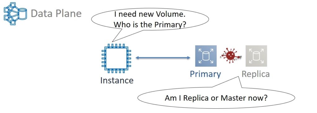
If Primary is alive, then you need to wait for the restoration of communication with him. And if the Primary has already died, then Replica itself should become the new Primary. Therefore, some kind of database all the time needs to track and remember who is Primary and who is Replica. The task is important but in essence simple. As a result, it was decided not to use tricky relational databases and exotic data types for Primary/Replica DB. The optimal solution was a simple Key-Value with support for integer, string, and boolean data types.
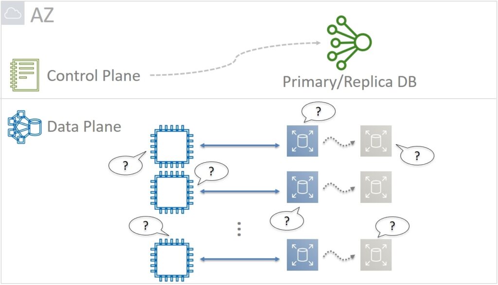
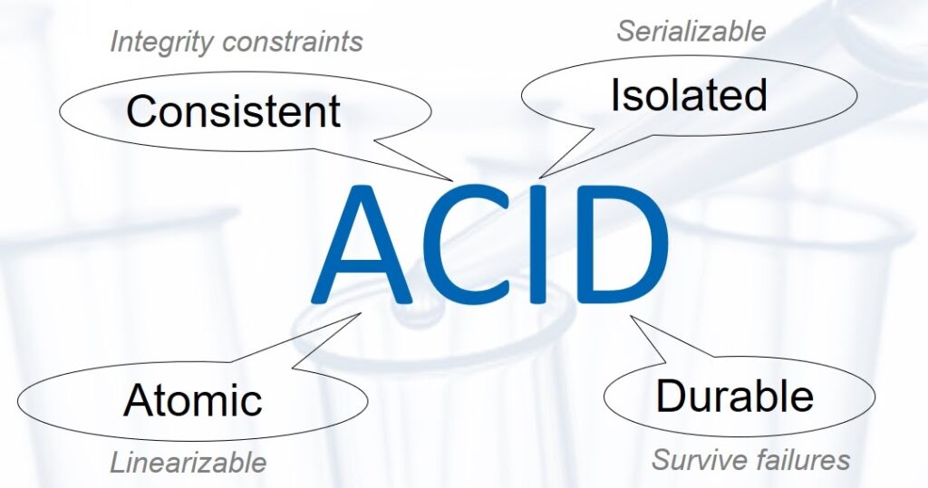
At the same time, Primary/Replica DB is critical for the performance of the entire service. Therefore, it must be extremely reliable and, as a result, ACID (Atomic, Consistent, Isolated, Durable) in the strict requirements of Linearizable Atomicity and Serializable Isolation.
High requirements for scalability, fault tolerance, and availability naturally force such a distributed database to be implemented. But this is easier said than done. After all, it was necessary to resolve the issue of data consistency between all components. In essence, it is to implement the database in the form of a distributed state machine. And the nodes of such a system must always come to a general consensus, that is, agree on the same data values that they store.
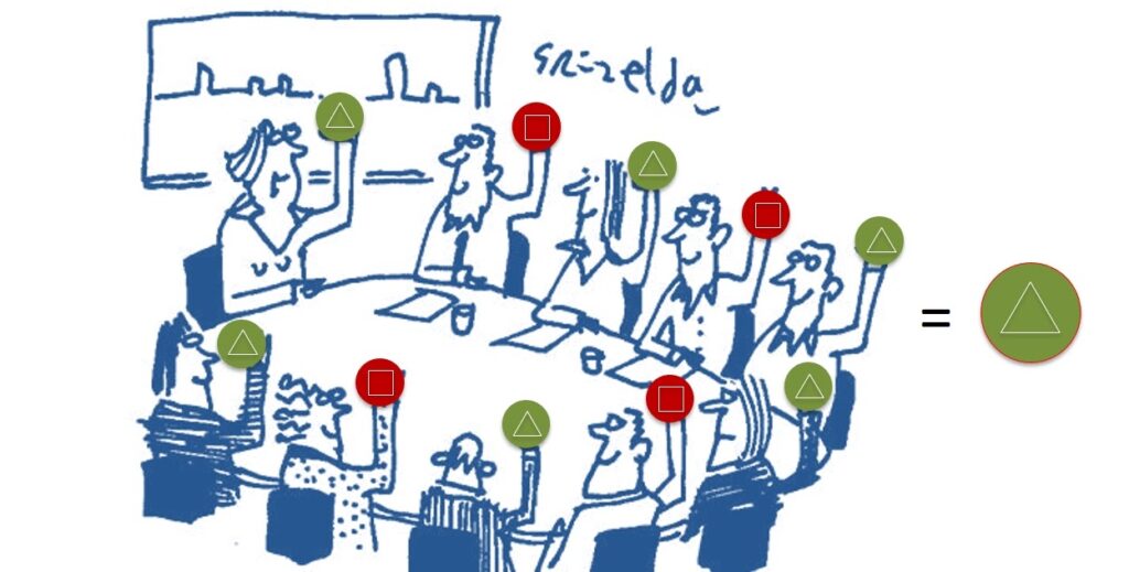
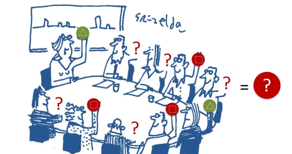
Of course, you can simply vote for all the components, and then recount them and make a decision, following the majority. But in reality, this approach does not work. We’re talking about the scale of the AWS cloud. The total number of components is huge and, purely statistically, they periodically break down, the connection between them sometimes disappears. Components recover from a failure, but slowly and may not have time to fully participate in the “vote”. So a simple majority-based approach will be unstable.
But there are tons of other protocols for building consensus: Paxos, Viewstamped Replication, Raft, Virtual Synchrony. In this case, Paxos was chosen. There are two reasons:
- Paxos has been used before;
- This is quite an "adult" approach; many different articles have been written about it. Google, LinkedIn, Microsoft have been using it for a long time and you can find information about what kind of rake they have stepped on, and vice versa – what advantages they got.
Paxos was implemented from scratch in the EBS Control Plane. As a result, we got a simple distributed ACID database, the blast radius of which is equal to the Availability Zone. But that wasn't enough either. And to reduce it, it was decided to implement Primary/Replication DB in the form of cells.
Step 2. Blast radius = Brick local
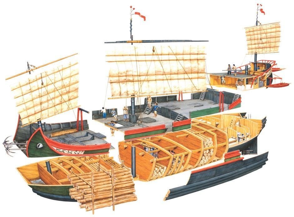
The cellular approach has been used by engineers for a very long time. Already in Medieval China, the hull of junok boats was divided into watertight compartments by partitions. In the event of a hole, only one or several of these chambers are flooded, but the boat remains afloat. Nowadays, the cellular approach is used everywhere.
But how many cells are needed for Primary/Replica DB per AP? Two, four, eight?
If there are only a few large cells, then the problems that sometimes arise will be large-scale. A large number of small cells will make problems more frequent in them. But such failures will be easier to localize and control. It was decided not only to follow this path but to take it to the extreme by assigning a Primary / Replica database to each EBS logical volume individually. And in the end, the blast radius should be equal to it.
Sounds great, but how do you put it into practice? The inspiration came from an interesting sea creature – the Portuguese boat or Physalia. Outwardly, it looks like a jellyfish, but in fact, it is a colony of a huge number of polyps of different types.
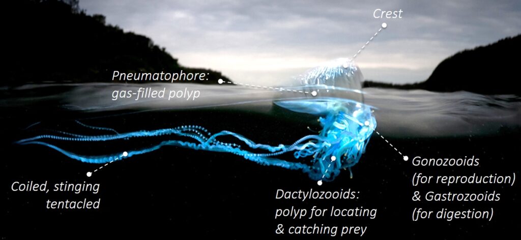
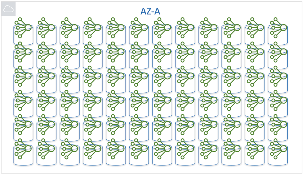
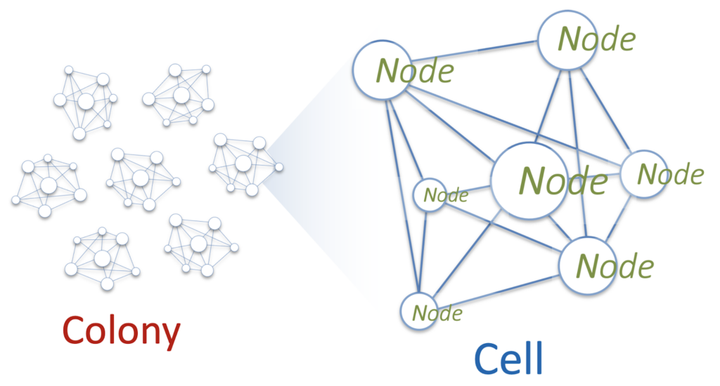
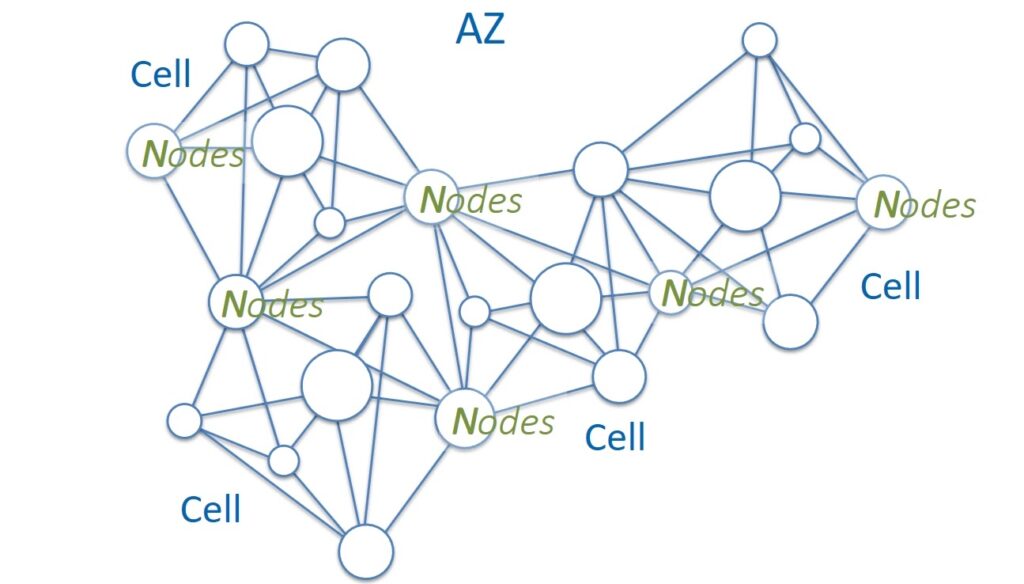
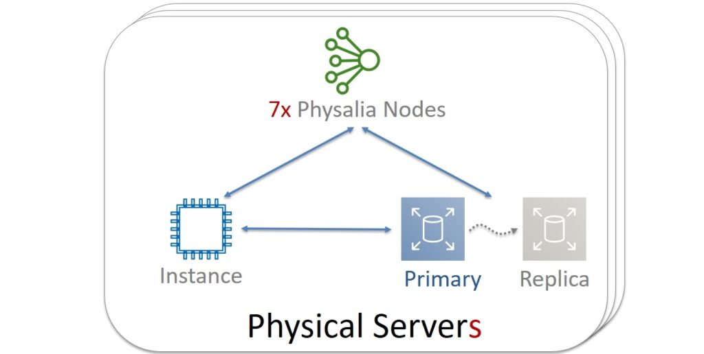
It was decided to build their service as a Physalia colony. Each of the millions of EBS volumes within one Availability Zone will be managed by its own Primary / Replica DB. And the database, in turn, will represent a cell consisting of several nodes. The cell is a distributed system operated by Paxos. These nodes will be located on different physical servers. And for reliability, you will need to make sure that the nodes of one cell never get to the servers common to them.
The task of the node will be very simple: participate in Paxos and store several tens of kilobytes of data. Then its CPU and RAM consumption will be minimal. And to save resources on a separate physical server, many hundreds of nodes of different Physalia cells will be launched. Architecturally, this looks like a many-to-many (mesh) topology.
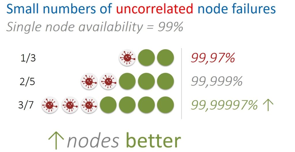
How many nodes will be optimal for one cell? A lot is bad, a little is also bad. Let’s first look at this question in terms of uncorrelated errors. For example, such errors occur when a physical server fails. This only affects specific nodes of individual cells. This situation is isolated and in itself does not cause damage to other servers and nodes.
It is also possible to approach the question in terms of correlated errors. For example, when a massive power failure occurs and many servers at once – and, accordingly, the Physalia node – become unavailable at the same time.
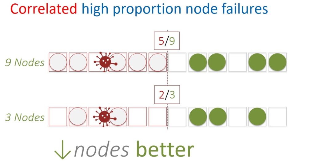
If you calculate carefully, it turns out that with a limited number of uncorrelated errors, the availability of a distributed system will be better with a larger number of nodes. And vice versa, if for some reason half or more nodes drop at the same time, then smaller cells will be more fault-tolerant.
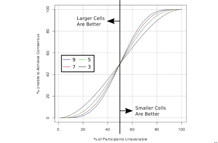
It is also worth taking into account that Paxos itself requires more resources with many nodes. In general, a reasonable cell size ranges from 5 to 13. In the end, 7 was chosen.
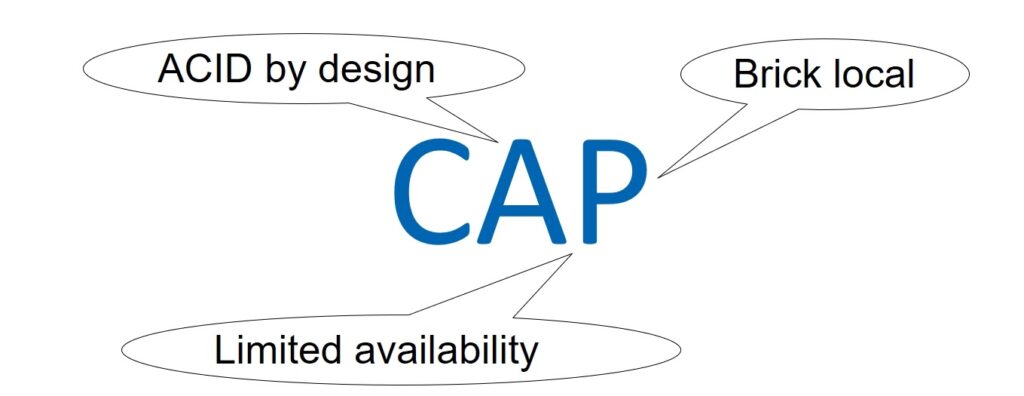
Of course, the Primary / Replication database must also be balanced in terms of integrity, availability, and resilience to partitioning. Let’s talk about the CAP theorem. However, we will not even try to discuss the issues of its correctness and applicability, this is a thankless task. It’s just that the CAP approach will allow everyone to use the terms Consistency, Availability, and Partition tolerance that are already clear to everyone.
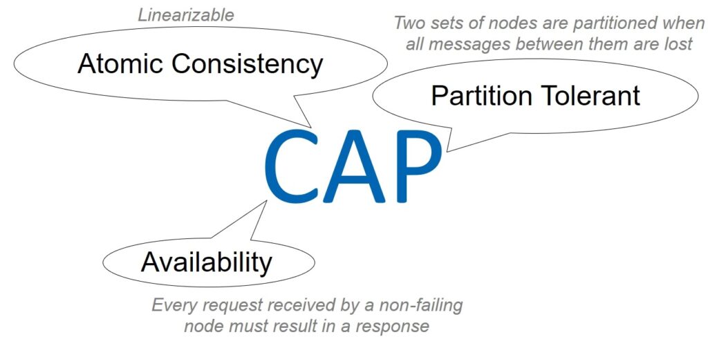
So, can we tolerate weak data integrity (Consistency)? Definitely not – it has already been decided that the database will be ACID, moreover, in the strict categories of serialization and linearization.
Further. Should our system be Available? Yes and no. The database does not need to be available to all clients, that is, all virtual machines. At a certain point in time, it is used by a specific virtual machine and the corresponding Primary / Replica pair. Our database does not care about all other potential consumers, so availability is interpreted here not globally for the entire AZ, but in a narrow sense.
And the third parameter is the resistance to network separation. Can We Work With Weak Partition Tolerance? Obviously not. The internal network of the AWS cloud is huge. Even if the most reliable network equipment and cunning protocols are used, on such a scale, purely statistically, packets will be periodically lost and delays will occur. This means that the nodes in the cells will be separated, ceasing to see each other.
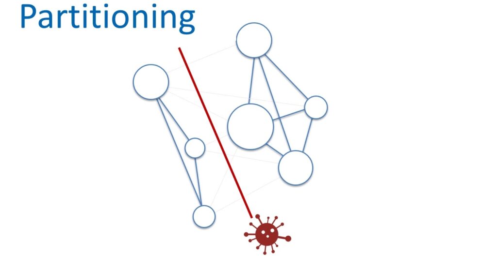
You just need to come to terms with this and build services with high resistance to network separation. But at the same time, it is necessary to control the scale of such a division.
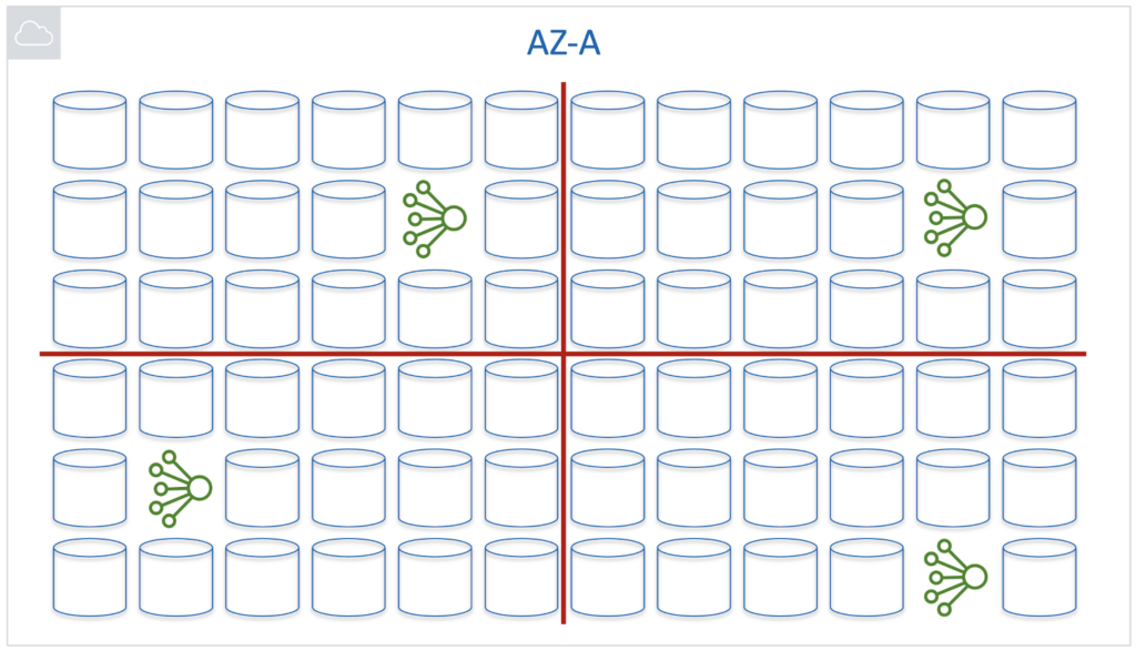
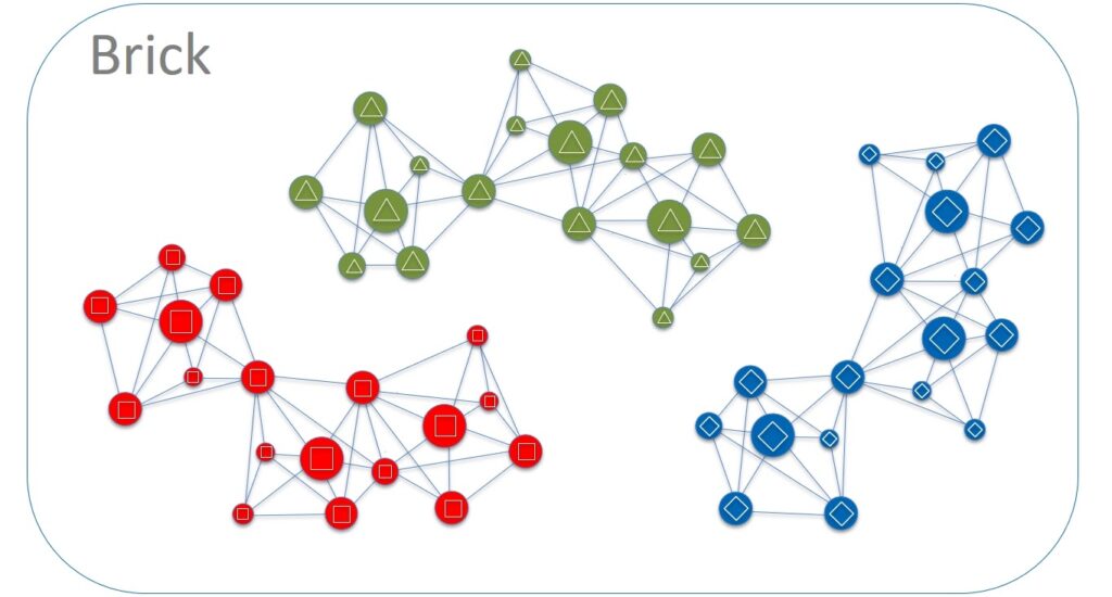
Let’s now look at a simplified physical network diagram. The equipment is mounted in server cabinets with Top of Rack switches. These switches are aggregated into groups called Bricks. These groups are connected to the network using Brick routers. Spine routers are responsible for the next level of aggregation. They interconnect network devices of the Brick level and are also used to connect to other Data Centers within the Availability Zone.
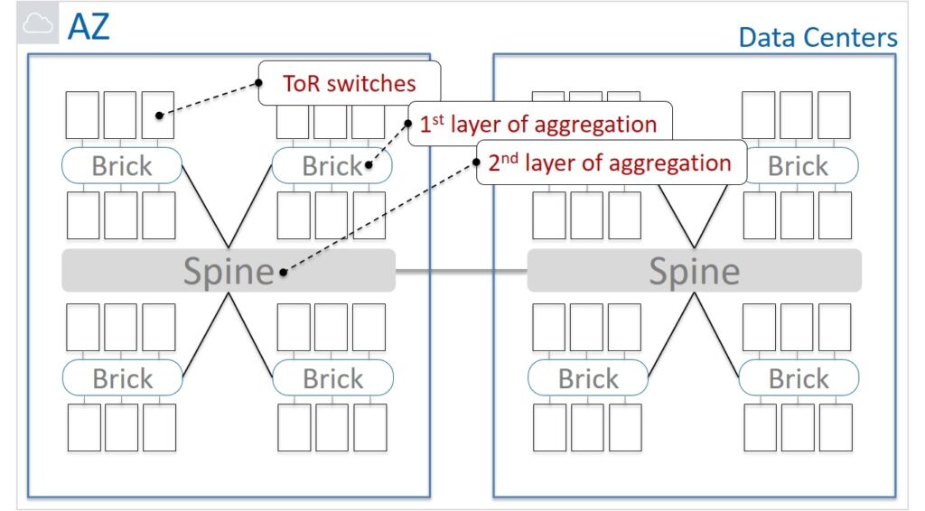
How far apart can the nodes of one cell be located? Within a server cabinet? In one Brick? Maybe in different Data Centers?
On the one hand, by placing the nodes as close as possible, we reduce the possibility of breaking the connection between the nodes. But the likelihood of correlated failures increases, which will affect more than half of the nodes in Paxos. On the other hand, the number of network hops (hops) negatively affects the partitioning resilience of the network. It is corny, more elements – the higher the probability that something will go wrong in them.
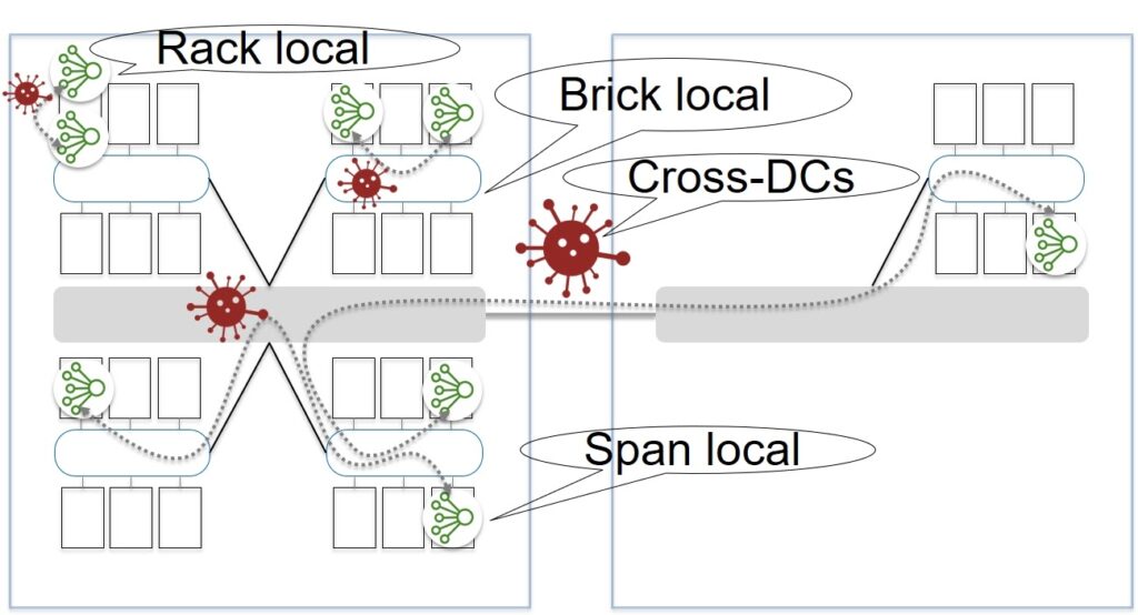
It was decided that the best option would be in which the nodes of one cell are located within the Brick. Thus, they laid in the architecture not global resistance to network separation, but Partition tolerance within the Brick. And as a result, we can talk about the CAP balance, taking into account the reasonable limitations of Availability and Partition tolerance, determined by the functionality of the EBS service itself.
Step 3. Blast radius = Color in a Brick
The situation has become closer to the ideal, but it still has not reached it. Let's further reduce the blast radius of our Primary / Replication database. Within Brick, hundreds of nodes of different cells live on each server, which communicates with thousands of other nodes. Let's divide the servers into groups and for simplicity let's call them different colors – red, green, blue, etc. It is worth choosing a small number of colors, say 4-6. And we also define two important rules:
- Nodes of one cell are always highlighted within the same color. There is no such thing that 4 cell nodes are located on red servers and the other 3 – on green ones.
- Any direct communication between servers of different colors is prohibited (Cross Colors Communication).
This isolation will allow us to isolate many failures. For example, potential problems while updating the code. An update is always done within a single color, say, red. If the update went well, we roll out the new software to the green servers. Etc. If any bugs appear, they are always isolated within cells located on servers of a certain color.
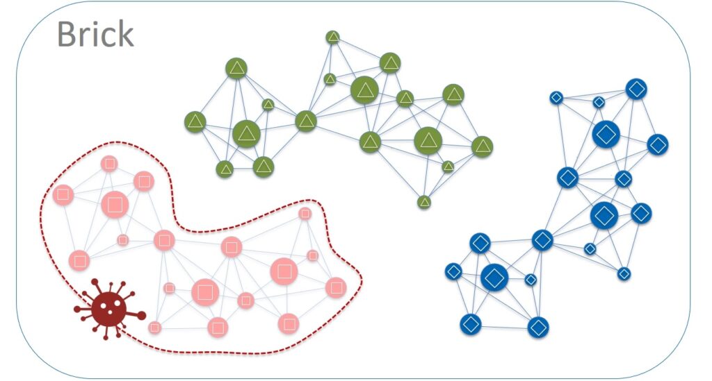
And now we can say that the blast radius is equal to one color in the group of server cabinets (Color in a Brick). But the system can be improved from the other side as well.
Step 4. Close placement = perfect latency
Virtual machine and storage services are very sensitive to network latency, which in turn depends on the physical and logical distance between elements. Obviously, the closer the service components are to each other, the better.
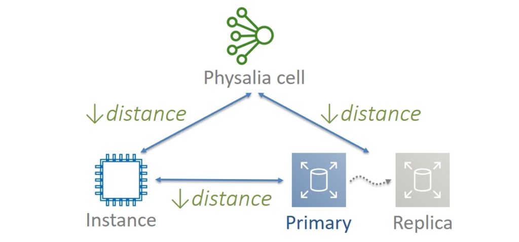
The locality principle was chosen for Physalia. The virtual machine, copies of the Primary and Replica data, as well as the nodes of the corresponding Physalia cell, are located as close to each other as possible, that is, on the same physical servers. But there are also reasonable limits. For example, to ensure fault tolerance, Physalia nodes must be on different servers. Replica should also be kept separate from Primary data. Therefore, it is important to run the virtual machine on the same server where the Primary data and one of the Physalia nodes are located.
In other words, put your eggs in the closest possible baskets. This will give less latency without compromising fault tolerance or durability. There is nothing wrong with the fact that some of the components will die together. For example, the Primary copy of the data will be temporarily unavailable with the virtual machine and one Physalia cell. While the virtual machine is being restored, it will be possible to resurrect the rest.
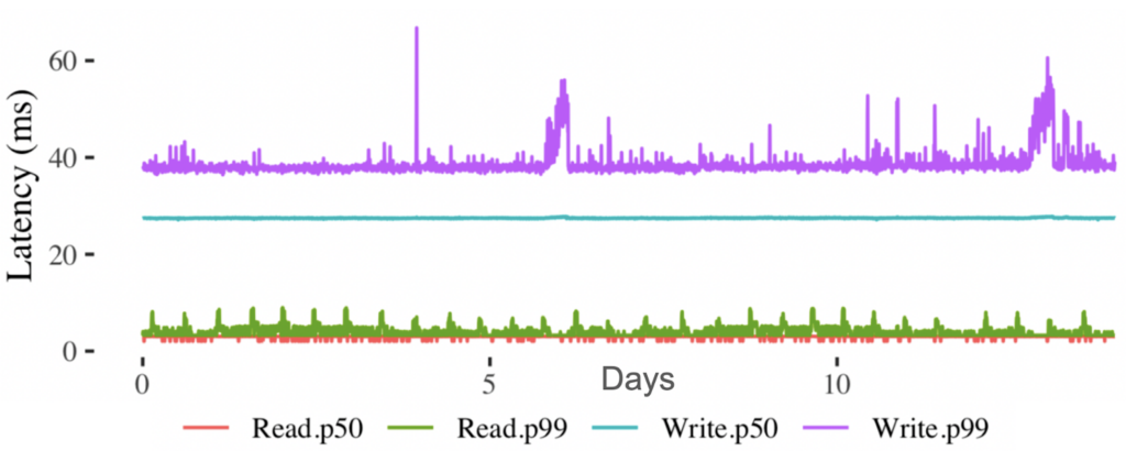
What have you achieved in the end? Let’s say we are starting a new virtual machine. In this case, the data in the Primary / Replica database is updated in no more than 60ms. This in itself is a good value, and considering that Paxos should work under the hood on 7 nodes, it is generally wonderful. When, for example, we restart the virtual machine and need to update the volume data, then reading from the database takes less than 10ms.
Step 5. Separate the Data Plane and Control Plane
Any service should be built in such a way that problems in the Control Plane have a minimal impact on the performance of the Data Plane. How was this achieved with Physalia? Let's remember what we already know. The EBS storage service has a Control Plane isolated at the level of each AP.
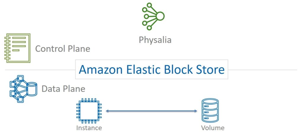
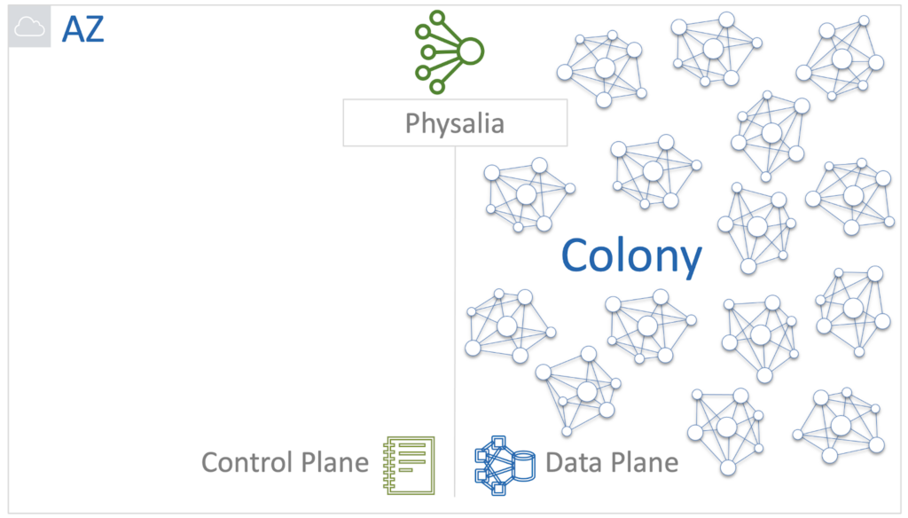
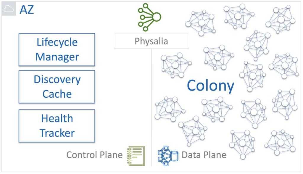
Physalia is part of the EBS Control Plane service. She, in turn, also has her own Data Plane and Control Plane. Data Plane is a colony of cells.
The Physalia Database Control Plane is a set of internal services that are responsible for the following functions:
- Create and delete cells;
- Always know where the cells and the corresponding nodes are;
- Repair if something breaks.
At Physalia, Lifecycle Manager, Discovery Cache, and Health Tracker is responsible for this.
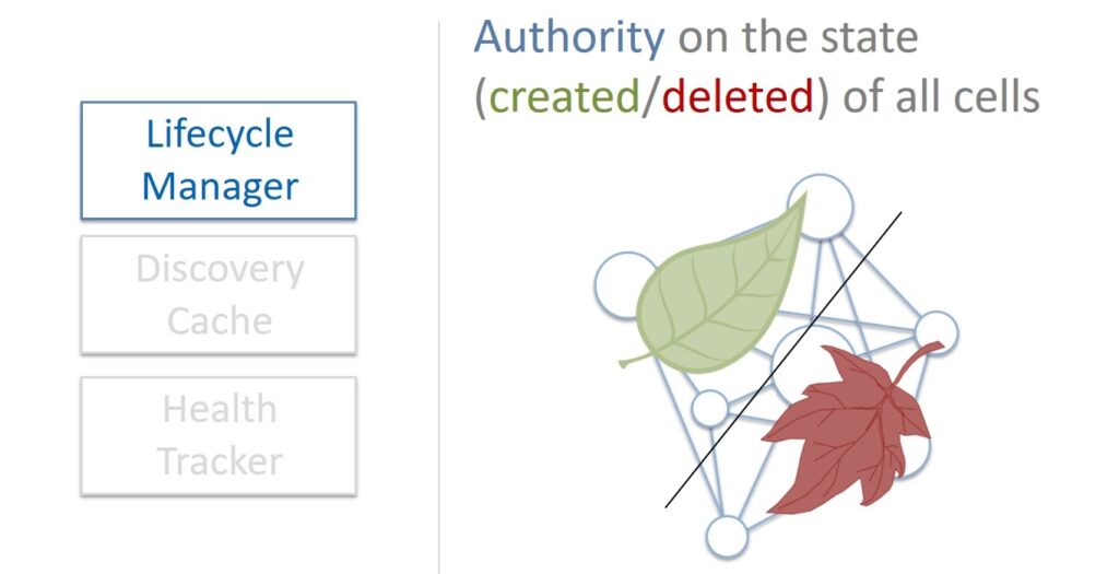
When a new data volume is needed, Lifecycle Manager creates a Primary / Replica database as a Physalia cell. He is also responsible for the deletion. Lifecycle Manager is the authoritative source of cell health information. You can ask him about it and the information received is always considered correct.
What happens if Lifecycle Manager crashes?
- If the problems are not big, Lifecycle Manager will fix itself, it is a self-healing system.
- If the Lifecycle Manager falls completely, then the situation will not be fatal either. All volumes that are already running will continue to work. Of course, it will not be possible to create and delete volumes for a certain period of time. But this is a short time because Lifecycle Manager is lightweight and recovers very quickly.
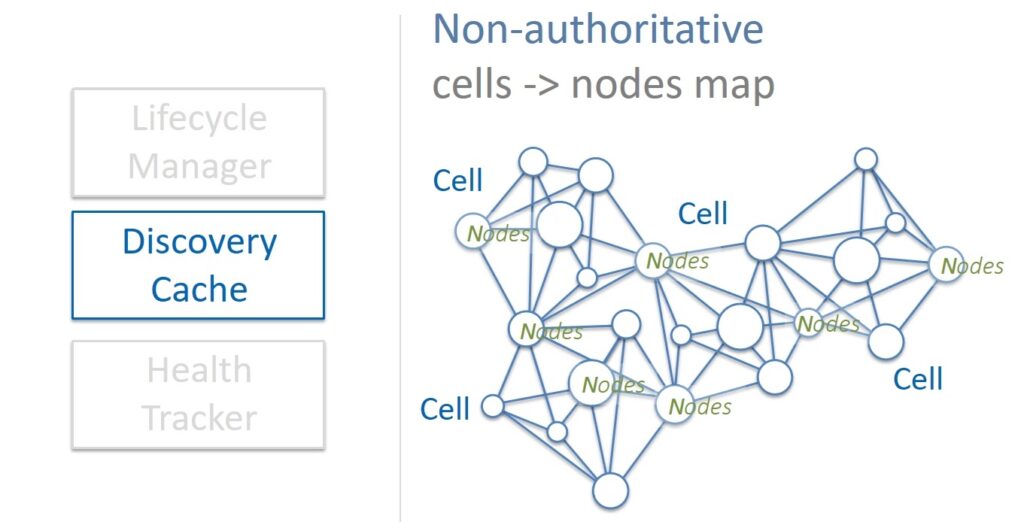
Discovery Cache is a cache that is a source of information about which cells correspond to nodes and on which servers they are located. Discovery Cache tries to keep track of this mapping, and most of the time it knows the current state of affairs. Sometimes, however, it happens that the cached information is outdated or incorrect for some reason. For this reason, Discovery Cache is considered an unauthorized source of information.
But this is not a problem. First, when the state changes, the cells themselves update the information in the cache. And secondly, the cache itself periodically scans the state of all cells in the colony and corrects the found inconsistencies. If some kind of failure occurs, it is possible to easily and quickly restore the data to the cache. In addition, Physalia cells are very small in size and therefore Discovery Cache requires small amounts of memory. Therefore, you can simply keep several copies of the cache – if one is broken, then we work with the other.
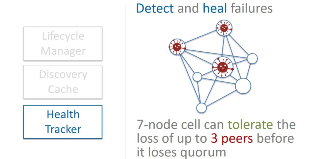
Health Tracker is the third component that keeps track of the health of the nodes in the cells. Physalia powered by Paxos consists of 7 nodes. Therefore, the cell remains operational if the majority of the nodes is alive, that is, four. Accordingly, without affecting the integrity of the data, we can afford the failure of up to three nodes.
A balanced Slow Repair approach should be followed. On the one hand, if some node stops responding and you need to try to fix the situation as quickly as possible, then in case of massive failures, this will spend too much of our resources. And the lack of resources, in turn, can affect the very possibility of recovery.
On the other hand, increasing the number of faulty nodes in a cell to three can be dangerous. Balancing on the brink is unwise. Therefore, when a node in a cell stops responding, it is not restored immediately, but they wait for some time, maybe it will come back. And only when you are finally sure that there are already two dead nodes in the cell, you should rush to make a replacement.
This is how the architecture is built, in which the Lifecycle Manager, Discovery Cache and Health Tracker components, i.e. Control Plane Physalia, have little effect on the availability and reliability of the cell colony itself, our Data Plane.
Results
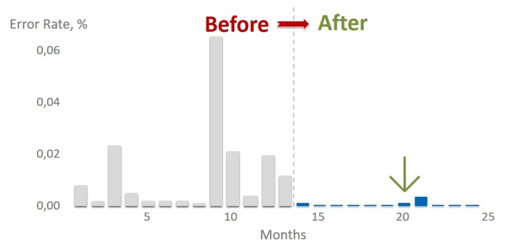
The implementation of Physalia fundamentally affected the number of errors in accessing Primary / Replica DB. This, in turn, fundamentally improved the stability and resiliency of the entire EBS storage service.
Of course, it is impossible to build a system in which there will never be failures at all. There are always human mistakes, unplanned massive iron failures occur, or the coronavirus has gnawed the wires. Therefore, it is always worthwhile to design systems to always be prepared for trouble and the ability to automatically recover, even in the event of exotic and rare problems.
Let there be few breakdowns in your systems, and your solutions will be stable and unsinkable by design. Like a catamaran.